
|
The CustomFISH wizard allows you to create break apart FISH designs to detect translocations in the human or mouse genome. The wizard asks you to define the target region using a gene name or other identifier and then walks you through the selection of parameters and options. You then submit the design to SureDesign and the program's algorithms select the oligo sequences based on the information you provided. When your oligo selection job is complete, you receive an e-mail notifying you that your design is ready to be finalized. Once you finalize the design, it is available for ordering.
To open the CustomFISH design wizard:
· At the top of the screen, click Create Designs > CustomFISH.
The wizard window opens to Step 1.
The steps of the CustomFISH wizard for a break apart design are described in detail in this help topic. The steps are:
Step 7: Finalize/Design Complete
In this step, complete the fields described below to define the design.
Design Name
Type a name for your design into the field. Alphanumeric characters, hyphens, underscores, and spaces are permitted. The name must be no more than 30 characters and it must be unique within your workgroup.
Species
Specify the species of the design. The default selection is H. sapiens, but CustomFISH designs can also be created for M. musculus.
To change the selection, click Select. The Select Species dialog box opens, allowing you to select the desired species.
Build
If multiple genome builds are available for the selected species, select the desired genome build in the provided drop-down list.
If no drop-down list for build selection is provided, that indicates that only one genome build is currently available for the selected species. That build is indicated below the Species field.
Specify the folder in which you want to save this design. The default selection is the top-level folder for your workgroup.
To change the selection, click Select to open the Select Folder dialog box, and mark the folder in which you want to save the new design. This dialog box lists the available folders within your workgroup and, if you are a member of any collaborations, lists the collaboration folders to which you have access.
Category
· Select Break Apart. This category is for the creation of designs for detecting break apart translocations.
NOTE For instructions on creating a dual fusion or single probe design, see Create a CustomFISH dual fusion design or Create a CustomFISH single probe design.
Design Type
Specify if you want the design to be shared or private.
· Select Shared to allow SureDesign to make the oligos in your design available to other SureDesign users. Selecting Shared does not mean that Agilent makes your design, your design information, or any of your personal information available to other customers.
· Select Private to restrict SureDesign from recommending your exact design to other users. Note that private designs could have a longer lead time as they will be prioritized below shared designs. Agilent reserves the right to sell oligos with overlapping or matching coordinates to other customers, regardless of shared or private design status.
Click Next to advance to Step 2.
In this step, define the target regions that you want to detect with the CustomFISH design.
In the Targets text area, type or paste the target identifiers directly into the text area. For break apart designs, you can enter the target identifiers using any of the three approaches described below.
· Approach #1: Enter identifiers for two targets – one that corresponds to the left side of the breakpoint and one that corresponds to the right side of the breakpoint. The two targets that you enter must be 1 bp to 200 kb apart on the same chromosome. Enter one identifier per line. See the table below for permitted types of target identifiers.
· Approach #2: Enter the identifier for a single target that overlaps the breakpoint. SureDesign will map the breakpoint to the center of the target. See the table below for permitted types of target identifiers.
· Approach #3: Enter the genomic location of the breakpoint, e.g. chr18:48577750-48577750.
Table: Permitted identifiers for defining targets
Identifier type |
Description |
Examples |
Target gene |
A single NCBI gene symbol, gene ID, or accession number. |
|
Genomic coordinates |
The genomic coordinates (UCSC browser format or BED format) for a single genomic region. |
|
Cytoband |
A cytoband identifier. |
|
Click Next to
advance to Step 3.
The fields and information provided on the Enter Parameters step depend on which approach you used for defining the target regions. See For regions defined by two targets, For regions defined by a single target, and For regions defined by a breakpoint location.
If you defined the target region by entering two target identifiers that flank the breakpoint, the Enter Parameters step allows you to set the size of the left and right padding regions. Because the size of each design input region needs to be at least 200 kb (or 400 kb for M. musculus), padding is required for targets that do not meet the minimum size in order to increase the size of the design input region. SureDesign includes the padding regions in the oligo selection job.
Fields and information for the 3' design region are displayed on the left side of the screen. Fields and information for the 5' design region are displayed on the right side of the screen.
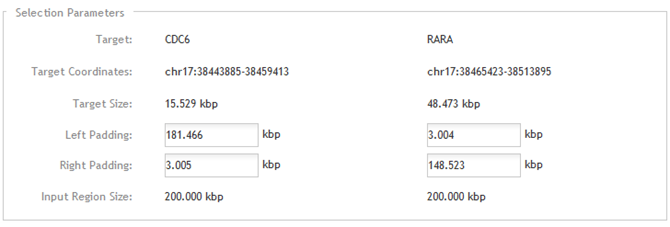
Target
This field displays the two targets as you entered them in the previous step.
Target Coordinates
This field displays the genomic coordinates of the two target regions.
Target Size
This field displays the size of the two target regions. If either region is <200 kb (or <400 kb for M. musculus), padding is required to increase the total design size.
Left Padding and Right Padding
Enter the sizes of the padding regions to the left and right of the targets.
Design Region Size
This field displays the size of the total design input region for each target, which includes the target region plus the left and right padding regions. If you change the value in the Left Padding or Right Padding field, the Design Region Size field updates automatically. The size must be at least 200 kb (or 400 kb for M. musculus).
If you defined the target region by entering a single target identifier that overlaps the breakpoint, the Enter Parameters step allows you to set the 5' and 3' gap sizes and the sizes of the 5' and 3' design input regions.

Target
This field displays the target region as you entered it in the previous step.
Target Coordinates
This field displays the genomic coordinates of the target region.
Reference Point
This field displays the coordinates of the midpoint location for the entered region. SureDesign uses the Reference Point as the approximate location of the breakpoint.
Target Size
This field displays the size of the target region.
5' gap and 3' gap
Enter the sizes of the 5' gap and 3' gap. The 5' gap is the region that lies between the 5' design region and the reference point. The 3' gap is the region that lies between the 3' design region and the reference point. Refer to the diagram on the Enter Parameters step (also shown in the image above). The sum of both gaps must be between 1 bp and 200 kb.
5' Design Region Size and 3' Design Region Size
Enter the size of the 5' design input region and the 3' design input region. Refer to the diagram on the Enter Parameters step (also shown in the image above). Each region must be between 200 and 2000 kb.
If you defined the target region by entering the coordinates of the breakpoint, the Enter Parameters step allows you to set the 5' and 3' gap sizes and the sizes of the 5' and 3' design input regions.
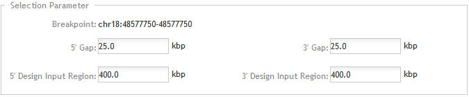
Breakpoint
This field displays the coordinates of the breakpoint.
5' gap and 3' gap
Enter the sizes of the 5' gap and 3' gap. The 5' gap is the region that lies between the 5' design region and the reference point. The 3' gap is the region that lies between the 3' design region and the reference point. Refer to the diagram on the Enter Parameters step (also shown in the image above). The sum of both gaps must be between 1 bp and 200 kb.
5' Design Input Region and 3' Design Input Region
Enter the sizes of the 5' design input region and the 3' design input region. Refer to the diagram on the Enter Parameters step (also shown in the image above). Each region must be between 200 and 2000 kb.
Click Next to advance to Step 4.
At this step, review the Target Details before you proceed to submit the design for oligo selection.
The Target Details table lists the following information for each design input region.
· Target ID - The Target ID column lists the target identifier as entered in the Define Targets step.
· Base Pairs - The Base Pairs column lists the total number of base pairs in the design input region.
· Position - The Position column displays the genomic coordinates for the design input region (including any padding) as link. Click the link to view the region in the UCSC Genome Browser.
Click View targets in UCSC to open the UCSC Genome Browser and see the genomic locations of the design regions.
Click Next to advance to Step 5.
At this step, SureDesign searches its database of catalog and shared CustomFISH designs to check for any existing designs that it can recommend to cover your design input regions. You then have the option of selecting one of the recommended designs or continuing to create your own. Because the recommended designs are already available in Agilent manufacturing, you can receive your design faster by selecting a recommended design.
The table at the bottom of the wizard window lists the recommended designs. These designs cover at least 70% of the design region. The information provided in the table is described below.
· Design ID - The unique ID number for the recommended design (shared customFISH designs only)
· Catalog ID - The unique ID number for the recommended design (catalog FISH designs only)
· Design Region - The genomic coordinates of the region covered by the recommended design
· Design Size - The total size of the design
· Overlap - The percentage of overlap between the design region for your design and the design region of the recommended design
· Action - Contains a link for downloading the design files
NOTE The Recommend Design step is divided into two substeps, one for each design input region (5' and 3'). The substeps are referred to here as Step 5a and Step 5b.
When you first advance from the Review Targets step to the Recommend Design step, you are asked to select a design for one of your two design input regions.
Your Probe Design 1 of 2
The table at the top of the window (labeled Your Probe Design 1 of 2) lists the following information.
· Design Name - In this table, the Design Name is the name of the child design that covers the first design input region. The default name assigned by SureDesign is FISH_<design name>_1. You can edit the design name as desired.
· Design Input Region - This column lists the genomic coordinates of the first design input region (including any padding).
To select a design for design input region 1:
Review the recommended designs to decide if any meet your needs. To help you decide, you can download the design files for a recommended design (click Download in the Action column) or view the overlap of the recommended designs with your design input region in the UCSC Genome Browser (click View Design Overlap in UCSC Browser).
Mark the check box next to the design that you want to use for the first design input region.
· If you want to use one of the recommended designs, mark the check box next to the design.
· If you want to continue creating your own design, mark the check box in the Your Probe Design 1 of 2 table.
Click Next to advance to Step 5b.
After you select a design for the first design input region, you are asked to select a design for the second design input region.
Your Probe Design 2 of 2
The table at the top of the window (labeled Your Probe Design 2 of 2) lists the following information.
· Design Name - In this table, the Design Name is the name of the child design that covers the second design input region. The default name assigned by SureDesign is FISH_<design name>_2. You can edit the design name as desired.
· Design Input Region - This column lists the genomic coordinates of the second design input region (including any padding).
To select a design for design input region 2:
Review the recommended designs to decide if any meet your needs. To help you decide, you can download the design files for a recommended design (click Download in the Action column) or view the overlap of the recommended designs with your design input region in the UCSC Genome Browser (click View Design Overlap is UCSC Browser).
Mark the check box next to the design that you want to use for the second design input region.
· If you want to use one of the recommended designs, mark the check box next to the design.
· If you want to continue creating your own design, mark the check box in the Your Probe Design 2 of 2 table.
To submit the design for oligo selection:
After you select a design for input region 2, submit the design to the SureDesign job queue and the SureDesign algorithms will select the oligos for your design.
Click Begin
Oligo Selection.
A message box opens indicating the e-mail address where Agilent will
contact you when the oligo selection job is complete. If desired,
you can enter additional e-mail addresses into the provided field.
Click OK
in the notification message to submit the design to SureDesign.
Your submission is placed in the SureDesign job queue to await oligo
selection.
The wizard automatically advances to Step 6.
At this point in the design creation process, SureDesign is processing your oligo selection job. The length of time required for SureDesign to complete the job depends on the number of jobs waiting in the queue and the size of your design.
Click Close Design Wizard. When you receive an e-mail from Agilent SureDesign notifying you that your oligo selection job was successfully completed, relaunch the wizard and continue creating the design:
Open the SureDesign Home screen.
Locate the design under Designs:
In Progress, and click the Continue icon ![]() .
.
The wizard window opens to Step 7.
NOTE You can monitor the status of your oligo selection jobs from the SureDesign Home screen.
In this step, click Finalize Design to finish the design creation process. Alternatively, if you want to make further edits to the design, click Modify Design to delete the oligos from the oligo selection job and return to the Define Targets step.
At this step, the information in the design summary panel is complete, and you can download and view the summary files to help you decide if you want to finalize the design or revise it further.
After clicking Finalize Design, the wizard window updates to the Design Complete step, and provides the following information:
Design Name |
The name of the design. Break apart designs consist of two child designs, one for each design region (5' and 3'). |
Design ID |
The unique ID number for the customFISH design. |
Catalog ID |
The unique ID number for the catalog FISH design. |
Design Region Size |
The total size of all genomic regions covered by the design. |
Coverage |
The percentage of nucleotides in each probe design that are covered by one or more oligos. The covered region is included as a track in the Covered BED file for the design. |
Use the action buttons at the bottom of the Finalize Design window to take
further action on the design:
· Click Order to open the Order dialog box, where you can submit a request to receive a price quote.
· Click Mark as Favorite to add the design to your list of favorites. The design will appear in the Designs: Recent and Favorites dashboard on the Home screen.
· Click Download to download one or more design files, including a formatted PDF report that summarizes key information on the design, oligos, targets, and the oligo selection job.
These action buttons are also available from the design details window.